
The New N1BUG EME Station
...When you're N1BUG, nothing you do is conventional...
(maybe that makes it more fun anyway)
I moved again in May 1999... back to the old QTH where I had been active before on EME. After a busy summer fixing up the house (and more busy summers to come!), I managed to build a small EME array in October. The array is 8 x 8 element quagis and cost about $100 to build (I did not have to buy all the parts. I still had some "junk" laying around). Here is some information about the antenna and my EME operation.
I wanted to put up something that would give at least 19 dBd gain. It had to be very inexpensive and it had to go up quickly... I wanted to be ready for the upcoming R1MVZ and J6MB expeditions! I made an attempt to build a 100 foot long yagi. Actually I did build it but it was destroyed while I was attempting to put it up.... it's a story I'm not going to tell too much about but I will say it was made entirely from junk and had a steel boom. My next idea was to put up some 8 element quagis. Eight of them should give between 19 and 20 dBd gain, but how to do this on my very limited budget?
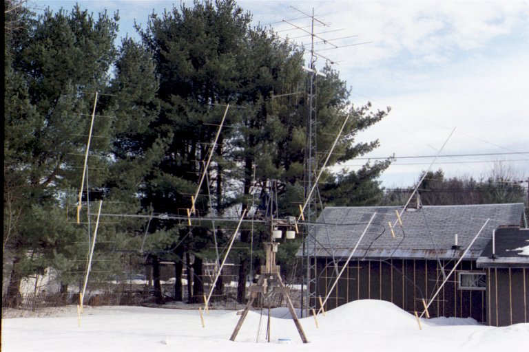
I ended up using PVC pipe for the booms, #8 AWG aluminum ground wire for directors, and wood spreaders with the required #12 TW insulated wire for the driven and reflector elements. Even though the booms are only 14 feet long they require a nylon support line; PVC is very flexible. Another interesting thing about PVC is its thermal expansion. When bright sun hits one side of a quagi boom, that side expands causing the antenna to look something like a banana, curved away from the sun. This doesn't seem to hurt performance too much and they always straighten right out when the sun goes off them. It is very strange to see! It cost about $75 to build the 8 antennas, using all new material.
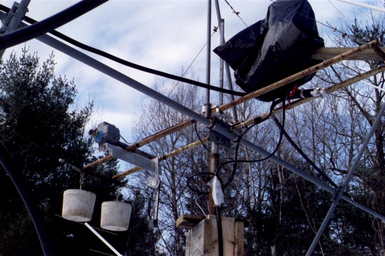
Here is what it looks like:
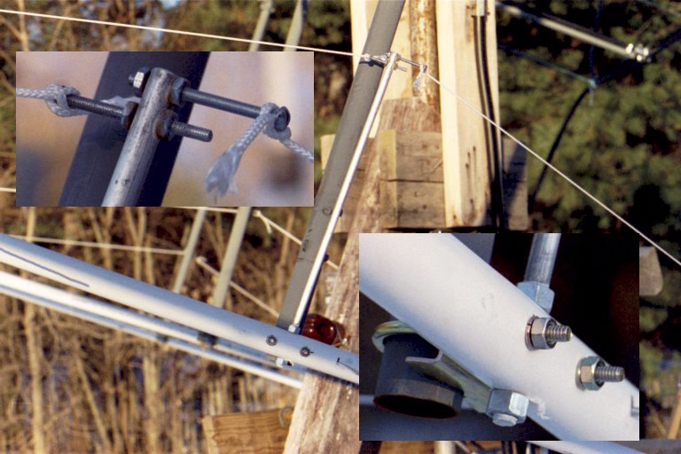
And the details of the boom support:
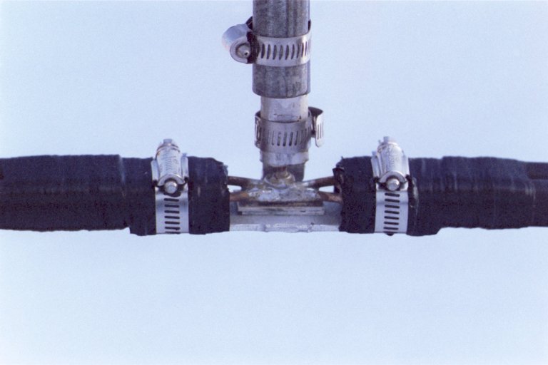
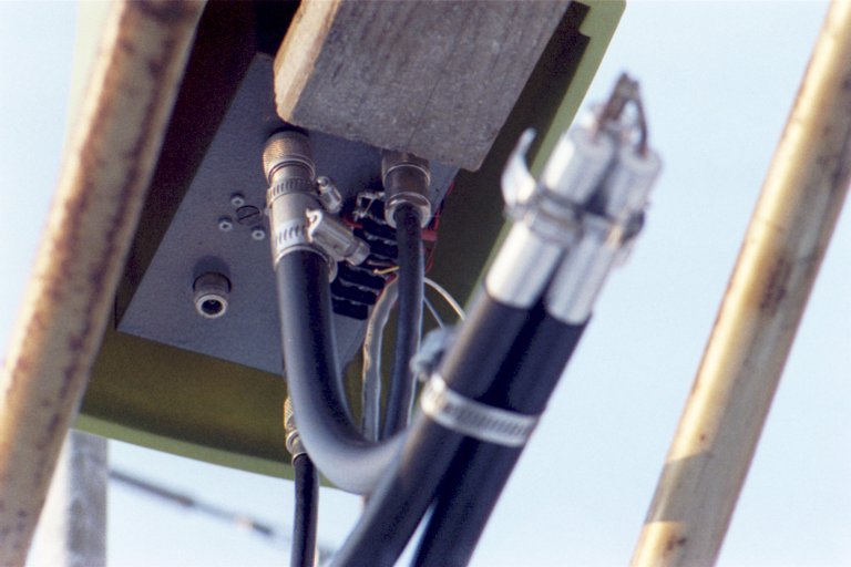
Phasing lines are 3/4" 75 ohm hardline, suspended at the back of the array so the lengths are as short as possible. There are no connectors! Phasing lines are soldered to the antenna driven elements, and all phasing line "junctions" are soldered and clamped. The preamp is mounted above the rotators for the lowest possible losses on receive.
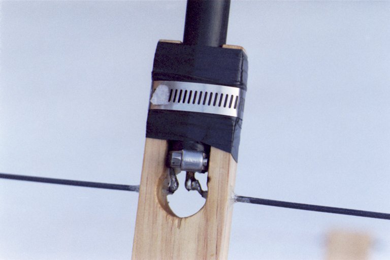
Driven element detail:
4-way phasing line junction:
The box containing preamp and relays:
The "double H" frame is made of 1.25 inch diameter steel TV-mast sections with a 1.5 inch section slid over the center 10 feet of the horizontal boom. A single Allicance U-100 rotor used like a winch serves as the elevation drive, while another U-100 with 6:1 chain drive handles azimuth. All this is built from bits of junk, including a sprocket and chain from an old bicycle.... very much like my old azimuth rotator back in the 1980's and early 90's. The azimuth mast is a length of "black iron" pipe. The "tower" is home made from hardwood, and it is just sitting on top of the ground.
Azimuth drive:
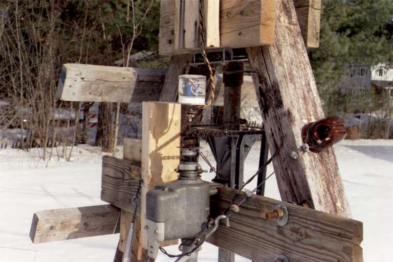
Elevation drive:
Again this is a very inexpensive antenna system. I do not believe EME has to cost a lot of money. If it did, I would not be QRV.
With 450 watts I was able to work stations with antenna gain of 16 to 17 dBd. The new PA with 4CX1500B was finished by the end of 2000.
When I built this array I planned for it to be just a temporary solution. I was hoping to put up an XPOL array with a little more gain after one or two years. This now does not look possible, so I will try to make some changes to this system for long term operation. This includes replacing the wood support structure with steel and raising the height of the array a few feet to keep it out of the snow during winter.
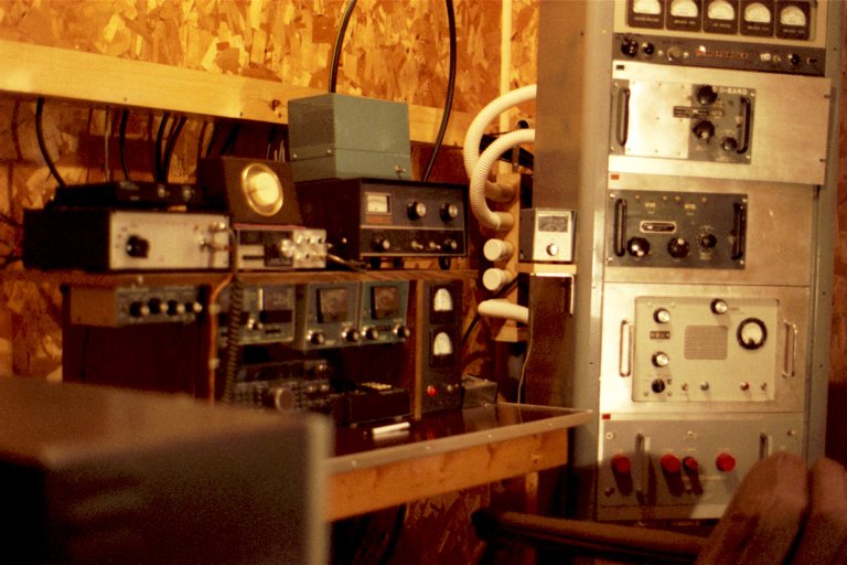
Finally, the ham shack:
This photo is a bit out of date.... there have been a number of changes, especially in 432 gear...
L to R, on top shelf... sequencer and band switch box with 6m transverter on top; Echo 70 432 rig with control box for rotor on terrestrial tower on top; Swan TV-2 2m transverter with Heath PS-23 power supply on top.
Mounted under shelf... Autek QF-1A filter; Heath HM-2140 HF power meter; Heath HM-2102 VHF power meter (6m); Heath HM-2102 VHF power meter (2m).
Sitting on bench... Kenwood TS-450SAT; AEA CK-2 memory keyer; homebrew 12v power supply; HF antenna switch.
In the rack, top to bottom... meter/control panel; AM-1178 432 amp (partly removed from rack); AM-912 222 amp; Comtron 2m amp; GE 6m amp. The small meter on the left outside of the rack is a Heath IM-4190 power meter used on 222 MHz. Power supply for all these amps is in bottom of rack, not visible behind chair. The white hoses behind the rack bring air from the manifold (mounted on the wall) to the amplifiers. There is a blower mounted beneath the floor that feeds air into the manifold.
Not visible... 222 transverter sits on top of rack. EME rotor and relay control unit in small rack below lower left corner of photo.
You may read my QSL policy.
![]()