
As used on the 2m array 1991-1994
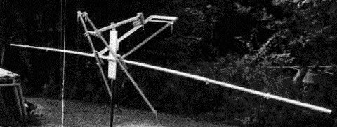
This first photo shows the completed main boom and elevation drive before the truss cables were added to the boom. Notice the sag. The antennas would be facing away from the camera in this view. The system is shown in the 0 degrees elevation position, jackscrew fully retracted. When the jackscrew is extended it pushes down on the rear of the array, this elevating the front. In part I did it this way so that I could park the arrray at 0 degrees elevation and feel secure knowing that the jackscrew was in its strongest position, fully retracted. Although it is not clearly visible in any of the following photos, the main boom slips through a larger piece of pipe about 2 feet long at the center, and rotates inside it. The short section of larger pipe slipped over the center section of the boom is attached to the boom to mast plate by means of U bolts. The boom is 30 feet long and is entirely made out of "black iron" pipe, with the center section 20 feet of 1.25" ID and the outer sections each 5 feet (exposed, with another 2 feet inside the center section) of 1" ID.
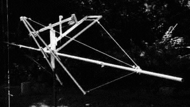
The next photo is a similar view after adding the truss cables for support of the main boom. Also the elevation readout pot and pendulum has been added (the pot is an ordinary 3/4 turn, 2 watt wirewound type and achieved accuracy of +/- 3 degrees). Notice there are three truss cables so the boom has some rear, top, and front support throughout the entire range of 0 to 90 degrees elevation. I later found it necessary to connect the outer ends of the pipes that support the truss cables (bottom rear in this photo) with a heavy cable, otherwise they tend to spread when the array is elevated past 45 degrees, allowing too much boom sag.
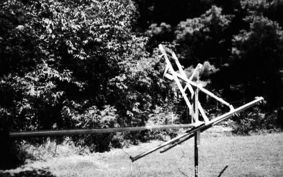
And a different veiw of it...
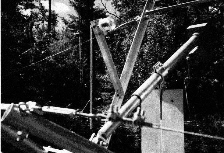
Now a closeup of the method used to mount the jackscrew and the elevation pot. The jackscrew is partly extended in this photo. The jackscrew pivot point is attached between two pieces of 4" x 4" x 3/8" aluminum angle stock that extend above the boom to mast plate. At the end of the jackscrew, a flat steel plate has been bolted across the top of the two pipes which support the rear boom truss, and to heavy aluminum angle brackets bolted to that plate hold the end of the jackscrew.
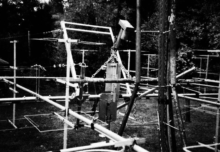
Finally, a view of the completed array ready to be pulled up the tower shows some additional detail not visible in the other photos. It would have been better if both pieces of aluminum angle bolted to the main boom to mast plate, but I did not have two pieces long enough for that. So one piece is bolted to the plate, then the two pieces are bolted together with a piece of 3/8" thick steel plate between to space them properly for attaching the hackscrew pivot bracket at the top. The array is in the 90 degree elevation position at this point. The chains are for pulling the completed array up the tower.
![]()