
Using the AM-912 Amplifier on 144 and 222 MHz
some notes by N1BUG
Caution: I had good results with this amplifier for some time after my initial modifications. Then I had a tube flash over in it (probably just a bad tube) and this damaged the socket, which is not so easy to replace in these units. Some time after that incident, C15 shorted. That is also not easily replaced. I have retired my AM-912 rather than repair it again. I believe these are reliable units if not pushed too far. I was running nearly 2500 volts (no load) on mine, which may have contributed to flashovers and the failure of C15.
The AM-912/TRC (or GRC) is designed as a plug-in for the T-302 transmitter. It makes a nice 250 to 400 watt
amplifier for 144 and 222 MHz with very few modifications. It does not have a built in power supply, so you will
need to supply the appropriate voltages for a 4CX250 type tube. Even so, with these being available from Fair Radio
for around $70 and often less at hamfests, it is an attractive unit considering it covers two bands. The information
on this page should allow most hams with some tube amplifier experience to get this up and running.
Modifications
The AM-912 was used in class C service. All that is required to use it in linear service (AB) is to remove several resistors. All are easily accessible so this is not a big job. It took me about 30 minutes. The resistors which need to be removed are designated in red on the following schematic. No RF modifications are needed for operation on either band. Part numbers are marked on the chassis so identification of these resistors in the actual unit is easy.
Notes:
After removing the resistors there must still be a connection between P2 pin 13 and C1.
There should also be a connection between P2 pin 19 and C2. You may or may not wish to
ground pin 19, depending on how you monitor plate or cathode current.
Whatever you do, pin 19 (cathode) must be connected to B- (the negative side of your high
voltage supply) and the negative side of your screen supply and the positive
side of your grid bias supply. I have pin 19 grounded at the AM-912.
I meter plate current by monitoring the voltage drop across a 1 ohm resistor in the power
supply. That resistor connects the (-) side of the B+ filter capacitor to ground, and it is
the only connection from the negative side of the high voltage supply to ground.
Be very careful with a scheme like this! If the 1 ohm resistor opens up, it could
be dangerous! Use several large power resistors in parallel to make up the one ohm resistor.
I use five 5 ohm resistors in parallel as a precaution; it is unlikely
that all will burn open at the same time unless there is some catastrophic event (in that case
the extreme current surge should blow the primary AC line fuses long before these resistors
would open up). Each 5 ohm
resistor is rated 25 watts, which is a lot of overkill for safety (each only dissipates a fraction of
a watt). The negative side of my screen supply and the positive side of my bias supply go
directly to chassis ground.
Disconnect the high voltage lead from P2 pin 1 and route it to a HV feedthru insulator or connector of your choice
mounted on the bracket that holds P2. Better yet, replace the HV lead with wire having a thicker insulation and
run it to your new HV connector.
Connect operating voltages as follows:
Ground to P2 pin 5.
6.3 VAC for the filament to P2 pin 3.
~ -50v bias (operating), -150v (standby) to P2 pin 18 (adjust operating bias for 100 mA idling current).
+250v to 375v screen to P2 pin 13.
+1500v to 2500v to your HV connector.
I soldered short leads directly onto the P2 contacts and ran them to a Molex connector which mates with a connector coming from my power supply and meter panel.
Connect a source of cooling air to the air inlet on the manifold just above the compartment housing the tube.
I mounted the unit to a standard 19" rack panel (7" height). If a large rectangular cutout is made
in the 19" panel and the front panel of the AM-912 loosened, the rack panel can be slid behind the existing
panel and secured in place with L brackets to the chassis.
Tuneup and Operation
With around 300v on the screen and 2 kV on the plate this amp will easily do 250 watts out on either band. With higher screen voltage it can produce in excess of 400 watts (I am not going to make any claims about IMD products here, other than to say it probably will not make any nearby VHF neighbors happy at 400w out). With 370v on the screen and 2.5 kV on the plate I have seen this amp do over 500 watts... but remember, I did not tell you to run it that way... I only said it will do it!
For power over 200 watts or so, replace the 4X150A with a 4CX250B or 4CX250R.
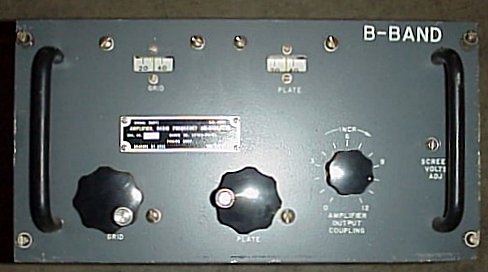
For 222 MHz, you should find the grid and plate tuning set to about 240 on the dials. Peak all controls for maximum RF power out (or peak the grid for maximum grid current and the plate tuning/coupling for maximum output). For AB1 (no grid current) it will only take a couple of watts to drive this amplifier. You can run more drive, up to 15 watts or so, for class C (grid current can be up to 30 mA) and get much better efficiency for CW operation. It has been a long time since I tuned mine on 144 MHz but I believe the grid and plate tuning were somewhere around 100 for that band. In any case it is a very easy unit to tune.
![]()