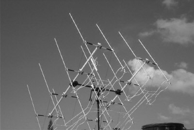
EA8FF 432 MHz crossyagi with open tube feeders
The main objective was constructing a highly efficient array for 432 MHz that wouldn't take too much space on the roof. The 16-er group I've put up is only 4 x 4 x 3 meter, and with the dual polarity and nearly zero feeder-loss, the result is surprisingly good, in fact I am receiving good echo's most of the time with my driver, which is only 35 W. For people with even less space a 4-er group would give you full EME-capability, with an antenna size that could fit on the corner of a balcony, turned in AZ and EL by inexpensive antenna-rotors. It would fit also inside the smallest 144 MHz-arrays.
The design of the single yagi was mainly done by cut and try: I wanted a cross-yagi with a total boom lenghth of 3m so that I could make 2 out of a standard 6m tube lenghth. I started to experiment with a single yagi: bending the open feeders in different directions, and measured the effect of this on pattern, gain and return loss. I concluded that the effect was nearly unmeasurable as long as the feeders didn't come as close as 30 mm to one of the elements.
With low noise amplifiers in the 0.2 dB-range available, it is desirable to keep the feeder losses near zero. This can be done by using "open tube feeders". I am using 6.3mm copper tubing, because it was the only size available here, but anything from 5mm up will give a total feeder loss of abt 0.05 dB in the 16-er array and 0.02dB in 4-er array. All parts of the feeders and dipoles are soldered together with T-joints and coated with white water-soluble acryl-based paint. A first coat of varnish was applied to prevent the acryl-based paint to oxidise the copper during the drying process.
I choose the stacking distances as 1300mm,you loose a little gain because the stacking has to be the same in
the V- as in the H-plane.
Here are the gains calculated by VE7BQH: single yagi:14.22 dBd
4-er group: 20.02 dBd (pattern plots)
16-er group: 25.96 dBd (pattern plots)
VE7BQH also states that optimum stacking for X-pol is 1333mm, with 0.07 dB extra gain.
713XY details
element  position  length    free space dim.
______   ______    _____     ____________
REF      00mm      347mm     341.5mm
DE       60        343       ----
D1       145       318       312.5
D2       321       308.5     303
D3       556       303       297.5
D4       815       297.5     292
D5       1098      295       289.5
D6       1378      292.5     287
D7       1674      290       284.5
D8       1961      288       282.5
D9       2262      283.5     278
D10      2554      283       277.5
D11      2811      279.5     274
Reflector and driven elements are 4mm alu, isolated through the boom.
Driven element is 8mm copper tube isolated through the boom.
Vertical and Horizontal elements are offset by 160mm.
Booms are 20 x 20mm alu square tube, 3000mm long.
Dipole construction:
Balun construction:
Phasing for 4 yagis:
Note: the length L1 is longer on the vertical for physical reasons. One extra bend is required to reach the
driven element, so a little extra length is needed.
Phasing for 16 yagis:
Note: the length L1 is longer on the vertical for physical reasons. One extra bend is required to reach the
driven element, so a little extra length is needed.
More photos of the EA8FF array
![]()